|
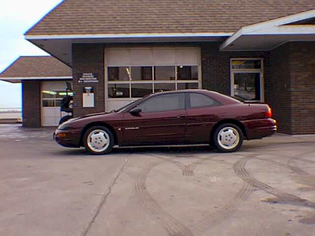
Here is the "Haunted" Sebring.
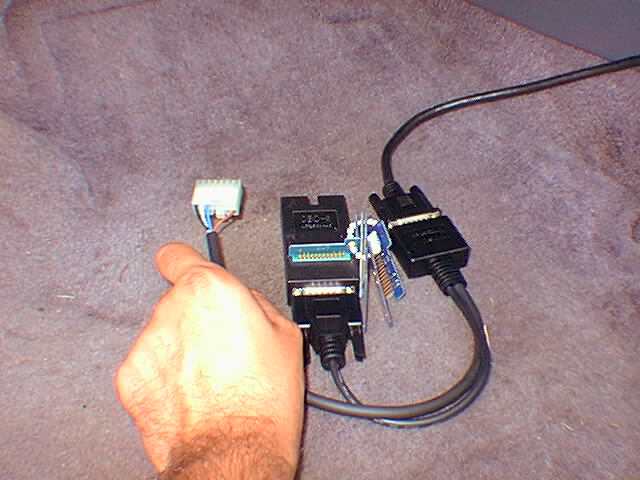
Fig. 1
Here is the special plug required for the scan tool to connect
to the PCM. Notice that it uses both and OBD II connector and a Mitsubishi
connector.
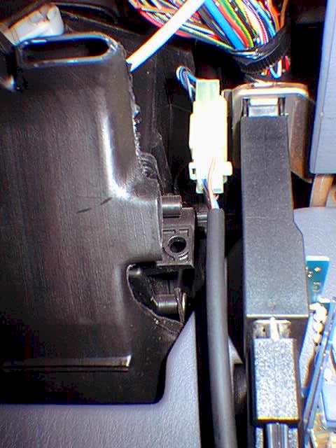
Fig. 2
This is a close up of the 2 plugs hooked up to the corresponding
diagnostic sockets under the driver's side dash.
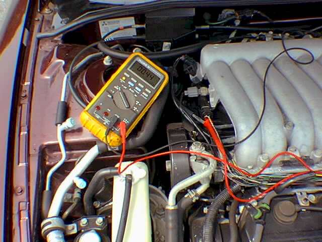
Fig. 3
Hmm...looks like the typical dead sensor stuck at mid range.
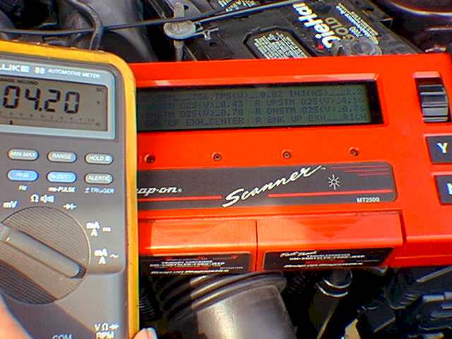
Fig. 4
What's this? More than a volt on the O2 feedback wire? Alas, our
ghost arrives.
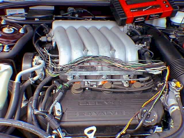
Fig. 5
Here was my road to nowhere digging inside the main engine harness
wiring loom.
]
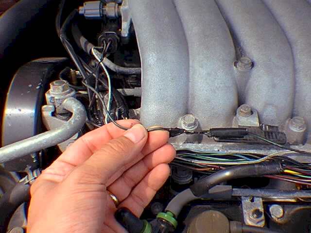
Fig. 6
Here is the rarely seen O2 sensor ground splice. Unfortunately
our ghost was not found here.
|
Vehicle : 1997 Chrysler Sebring
2dr. Coupe
Powertrain: 2.5 Liter V-6 4Spd. A/T
Mileage: 46,721
Symptom: Mil On
Problem Overview:
It all started when an employee asked me if I would "take a peek"
at his car. Our employee was concerned because his Malfunction Indicator Lamp,
(MIL), was on and he wanted to know how serious the problem was. With the
growing trend towards intermittent problems these days, I was hoping that
this "peek" wouldn't turn into a case of "peek-a-boo".
Vehicle Specifics:
The Chrysler Sebring is sort of a Chrysler-Mitsubishi hybrid product.
Since it is a 1997, the vehicle is OBD II compliant and has multipoint fuel
injection. Fuel injection is normally carried out once for each cylinder
for every two rotations of the crankshaft. Fuel delivery is determined by
a speed density system via the MAP sensor. The vehicle utilizes 4 Heated
Oxygen sensors.
Diagnosis:
Starting with the usual under hood inspection, everything easily
visible appeared to be in order. No sensors unplugged, no new bodywork, etc.
The next logical step with the MIL on was to check for codes and analyze scan
data. I feel as though I learn something new everyday and connecting our
Snap-On Scan Tool to this car proved that philosophy. On all the prior OBD
II cars I have tested, I have only needed an OBD II type connector. This car
was unusual in that it requires that you connect both the OBD II and Mitsu-1
connectors in order to communicate with the PCM. They are mounted side by
side below the dash between the steering column and center console. (Figs.
1 & 2). Once the scan-tool was connected I pulled codes. Only one
code was logged, P0134 "rear bank up stream H02S stays at center". After
a quick check for service bulletins we updated our employee on what we knew
so far. He asked us to halt further testing until he could call the local
Chrysler dealer. Our employee recalled that about a year ago the dealer replaced
one of the O2 sensors under the Chrysler 3 year / 36,000 mile warranty. The
question was: Which O2 sensor? The dealer pulled up his vehicle's history
and told him that the front upstream O2 sensor was replaced in the past, not
the rear, and that the vehicle was out of warranty anyway. Now some of you
are probably wondering...3/36 warranty? The new OBD II emission rules mandate
2 years and 24,000 miles new car warranty on all emission related items,
right? (Note that the PCM and catalytic converter are covered to 8/80)
Right, but even though the O2 sensor has a minimum warranty of 2/24 the Chrysler
3/36 bumper to bumper warranty overrides. Another warranty tid-bit that causes
confusion is the warranty on a replaced part at a dealership and how that
effects the 3/36 warranty. Typically, if a part is replaced at the dealership
under new car warranty, the part is covered for the remainder of the 3/36
warranty or 12/12 from replacement date, whichever provides greater coverage.
I have got a few customers some "free" parts under this loophole. It basically
means that if a part is replaced under the 3/36 warranty, then fails after
the 3/36 expires, the part still carries a 12/12 warranty from date of installation.
Anyway, back to our O2 sensor problem. A quick read of the datastream revealed
that the rear upstream O2 sensor was fixed at .44 volts.
A Note Of Warning:
Many scan tools will incorrectly display the names of the various
O2 sensors. OBD II terms specify that the heated upstream O2 sensor on the
bank with cylinder #1, be called or abbreviated "Heated Oxygen Sensor Bank
1 Sensor 1" Not all scan tools follow this logic. Quite often, the sensors
are named left, right, bank 1, bank 2, etc. Worse yet, are the several cars
I have seen where Bank 1 and 2 are reversed. Took a bit of hair pulling the
first time I got stuck with that one. I wish I could have billed the scan
tool company or auto manufacturer for the time I gave away on that job! When
is this industry ever going to be organized? And if you think were moving
towards industry standardization, wait till you try to call the dealer and
order one...Which sensor is considered left on a car with a transversely mounted
engine? Be sure to disconnect each sensor to watch for the change in the
datastream. This way you can be sure that your diagnosing the right sensor
in the first place.
Ghost Stories:
The connector for the rear upstream sensor is easily located on the
main engine harness support bracket. The wire colors are: BK/DG for sensor
ground, WT/BK for O2 signal, BK/RD for heater power and BK for heater ground.
Voltmeter testing was fairly cut and dry: 13.5 volts on the heater wire,
.03 on the grounds and .44 volts on the signal wire. A shot of carb. cleaner
in the fresh air hose did not cause any increase in sensor voltage. Pulling
the brake booster vacuum hose did not drive the sensor down either. It seemed
like the typical dead sensor. All of a sudden, while watching the .44 fixed
voltage value in the datastream, I saw a reading of between 4.21 and 4.98
volts! Wow, almost 5 volts on the sensor signal wire! Then, after a few minutes,
the high voltage reading disappeared and it was back to .44 volts. Where did
the mystery 5 volt ghost go, and, better yet, where did he come from? I decided
not to trust scan data alone and reconnected the voltmeter to the signal
wire. Still my ghost was gone, just a dead sensor at .44 volts, (Fig. 3).
I shut the car off and went to grab a coffee. Perhaps it was a lack of caffeine,
I thought. About a ½ hour later I started the car and began wiggling
under hood wire looms while simultaneously watching the voltmeter and scan
tool. After wiggling the main engine harness the scan-tool and voltmeter shot
up to 4.2 volts, (Fig.4). The ghost was back. I began to theorize that somewhere
in the main engine harness the O2 sensor signal wire was chaffed and rubbing
against a sensor's 5V reference wire. Sounds possible right? Well, as Fig.
5 will show, I had the entire loom cut open and exposed almost all the way
to the PCM. I even found the sensors ground splice but it was fine, (Fig.
6). Not a single wire was chaffed or damaged in any way. Just out of
sheer luck and determination I noticed a peculiar pattern to our ghost. He
had a schedule. I started to notice that the 4-5 volt ghost came only once
per ignition cycle. A stop watch helped me prove another pattern. The ghost
voltage came after exactly 3 minutes of engine run time and only stayed present
for 2.5 minutes. Although I found no published information about this, it
sort of "rang a bell". In a past Aspire training class I recall my instructor,
Bill Cahill, talking about OBD II strategy. When an O2 sensor fault code
is stored the PCM can internally apply a reference voltage out the normally
input wire to help figure out if the sensor is plugged in or to check the
integrity of the circuit. I noticed that if the sensor were unplugged the
voltage would still appear on schedule. It would appear that the PCM is intentionally
sending voltage down this wire as a circuit test. Had our employee continued
to drive the car, the PCM may have set more O2 related codes as it proved
out the circuit.
Endings And New Beginnings
In the end what I thought was a wiring problem was some little known
strategy of the PCM. You might even call it "ghost strategy". I retaped
the wiring harness, replaced the O2 sensor and am happy to say the MIL is
off. That's enough ghost chasing for one day.
 Mark Giammalvo

|

